

The parking scene is one of the earlier and more extensive scenarios where autonomous driving lands, and the automatic parking function is useful for many owners. Especially for novice drivers, in the stage of driving technology is not yet proficient, facing the relatively difficult driving scenario of parking, if the vehicle equipped with automatic parking function to achieve auxiliary parking or automatic parking will greatly improve driving safety and efficiency. Therefore, in recent years, automatic parking technology has also developed rapidly, from the beginning of semi-automatic to fully automatic parking to the launch of memory parking and valet parking in recent years, its degree of automation is becoming higher and higher, and scene adaptability is becoming stronger and stronger. So what is the development stage of automatic parking technology, which key technologies are included, and whose automatic parking system is best used on the market now? This article will take you to sort out and answer these "dry goods" questions.

Development history
1.1 Development stage
According to the evolution of the degree of automation, automatic parking can be divided into semi-automatic parking, fully automatic parking, memory parking, autonomous valet parking four product forms, according to the sensor and the use of different scenarios, fully automatic parking can be divided into ultrasonic based automatic parking, ultrasonic fusion camera fully automatic parking, remote control parking three forms. With the continuous iteration of automatic parking technology, the practicability of automatic parking function is becoming stronger and stronger.
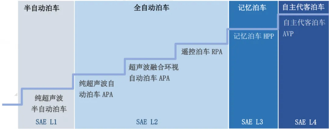
Automatic parking development stage
1.2 Function Definition
Semi-Automatic Parking (S-APA)
Semi-Automatic Parking Assist (S-APA) realizes parking perception based on the ultrasonic sensor of the vehicle, provides parking information to the driver, and carries out path planning. The system automatically controls the vehicle steering system. The driver only needs to follow the prompts of the dashboard to control the vehicle longitudinally.
Semi-automatic parking requires real-time driver supervision and control of gear, acceleration and deceleration, corresponding to SAE L1 level.
Fully Automatic Parking (F-APA)
Compared to semi-automatic Parking, Full-Automatic Parking Assist (F-APA) is more intelligent. The fully automatic parking system can control the vehicle horizontally and vertically, while requiring the driver to continuously monitor and effectively take over the vehicle to ensure parking safety, and belongs to the SAE L2 level parking assistance system.
Remote Control Parking (RPA)
RPA (Remote Parking Asist) remote control parking assistance system is developed on the basis of APA automatic parking technology, and the configuration scheme of on-board sensors is similar to the first generation. It was born to solve the awkward scene of difficult to open the door of the car after parking, such as in the parking space on both sides of the car, or in the relatively narrow parking room.
RPA allows the user to use a remote control device (mobile phone or key) to control the vehicle within a certain visual range outside the car for parking, parking, straight in, straight out and other functions, and the driver must always monitor the status of the vehicle during the entire process.Compared with APA, the biggest difference of remote control parking RPA is that the driver is always outside the car during the parking process, if some safety risks are encountered at this time, the driver is not capable of timely safety handling in the car.
Memory Parking (HPA)
On the basis of fully automatic Parking, Home-Zone Parking Asist (HPA) can autonomously complete parking in and out operations in relatively longer distances and more complex environments. Based on SLAM (Simultaneous Localization and Mapping) technology, memory parking uses body sensors to learn, record and store users' commonly used exit location, parking location and parking path. The environment feature map of the common parking path is established. When the vehicle passes through the place again, the system will reproduce the user's parking path to replace the driver to complete the last distance of low-speed driving and parking in the parking lot. When the external environment changes greatly and the memory parking function cannot be realized, the memory parking system will require the driver to take over the vehicle or return to the original position, which corresponds to the L3 level of SAE classification.
Valet (AVP)
Autonomous valet parking means that the user gets off at the designated drop-off point, gives parking instructions through the mobile APP, and the vehicle can automatically drive to the parking space of the parking lot after receiving the instructions, without user control and monitoring; The user gives the pick-up instruction through the mobile APP, and the vehicle can automatically drive from the parking space to the designated pick-up point after receiving the instruction; If multiple vehicles receive parking instructions at the same time, multi-vehicle dynamic automatic waiting to enter the parking space can be realized. In the process of automatic driving, the vehicle shall be able to comply with the road traffic rules, or the on-site traffic rules formulated by the parking lot operator.
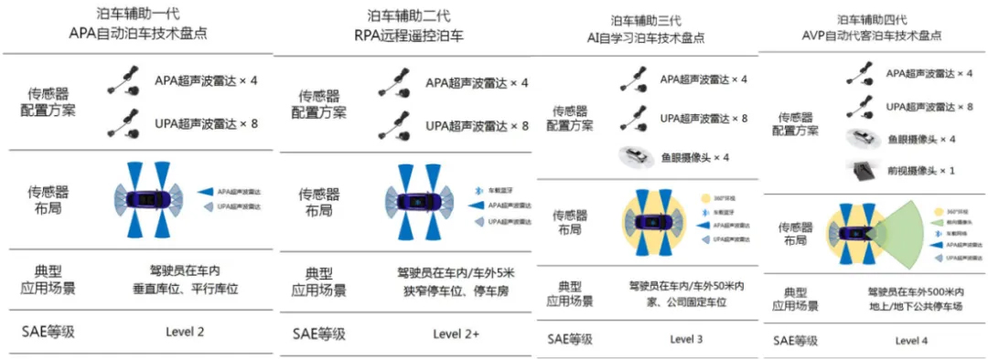
Evolution of automatic parking solutions

System composition

System composition
2.1 Sensor
APA sensor configuration has two mainstream schemes, one is based on pure ultrasonic radar, the other is based on holographic image and ultrasonic radar fusion perception scheme. However, the pure ultrasonic perception scheme only has spatial information, and can only identify the parking Spaces determined by the boundary cars and curbs, and does not support the parking Spaces determined by the parking lines. Parking Spaces cannot be detected in the absence of obstacles. According to incomplete statistics, among the vehicles equipped with APA functions in China, the proportion of holoimage-based and ultrasonic fusion schemes has increased year by year, from 6.8% in 2018 to 48.4% in January-May 2022. With the improvement of the computing power of the computing platform and the requirements of users for multi-scene landing schemes, the ultrasonic and visual fusion perception scheme will become the mainstream automatic parking scheme in the market.
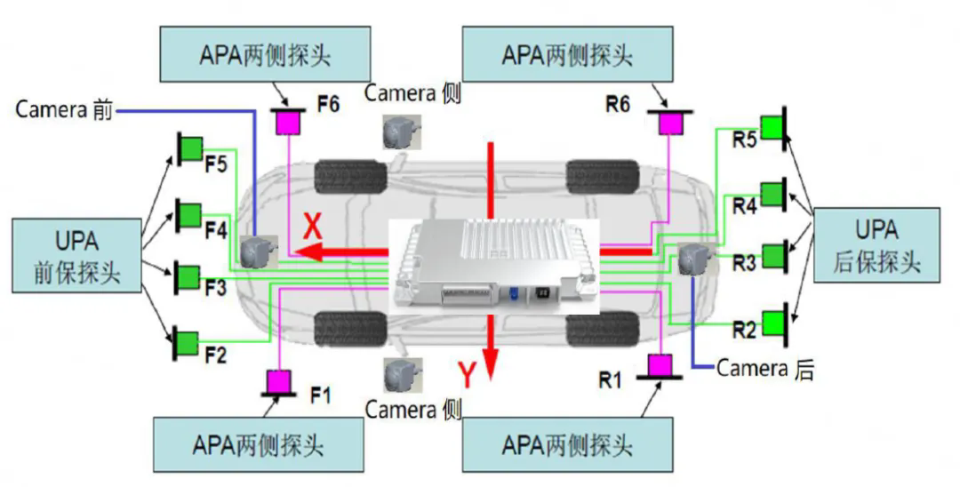
Automatic Parking Sensor Solution
Automatic parking mainstream car end sensor configuration scheme

Sensor comparison

2.2 Controller
Parking controller is responsible for processing and analyzing the information collected by the sensing system, obtaining the current position of the vehicle, the location of the target and the surrounding environment, judging whether parking conditions are available according to these parameters, calculating the optimal path planning, and generating the corresponding control instructions. And through the vehicle network, the steering torque, Angle information and other information required in the parking process is sent to the relevant actuator in the form of electrical signals, and the information that needs to be displayed to the driver is notified to the HMI end according to the output logic and order.
With the improvement of the level of automatic parking, the types and numbers of sensors required for each program are increasing, and the demand for data processing is also increasing. In general, ultrasonic data can be processed using a microprocessor (MCU); Camera data processing includes traditional computer vision methods and deep learning methods, which need to use the central processing unit (CPU), graphics processing unit (GPU), digital signal processing unit (DSP), neural network processor (NPU) and other processing units on system-on-chip (SoC). Millimeter wave radar and liDAR data require more powerful SoC chips for processing.
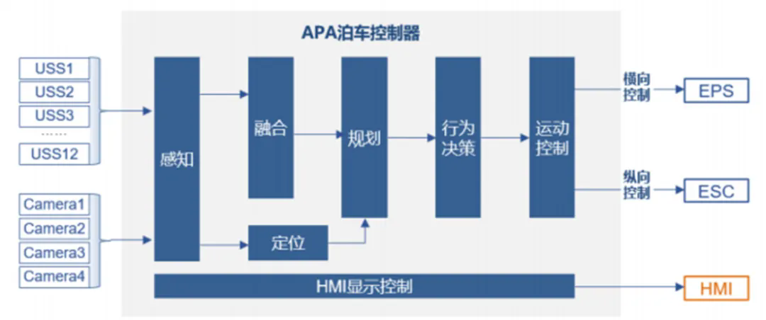
Parking controller architecture Source: Blue Book of Automatic Parking Industry Development (2021-2025) -Gaogong Intelligent Vehicle production Currently on the market mainstream driver assistance function domain control design scheme:
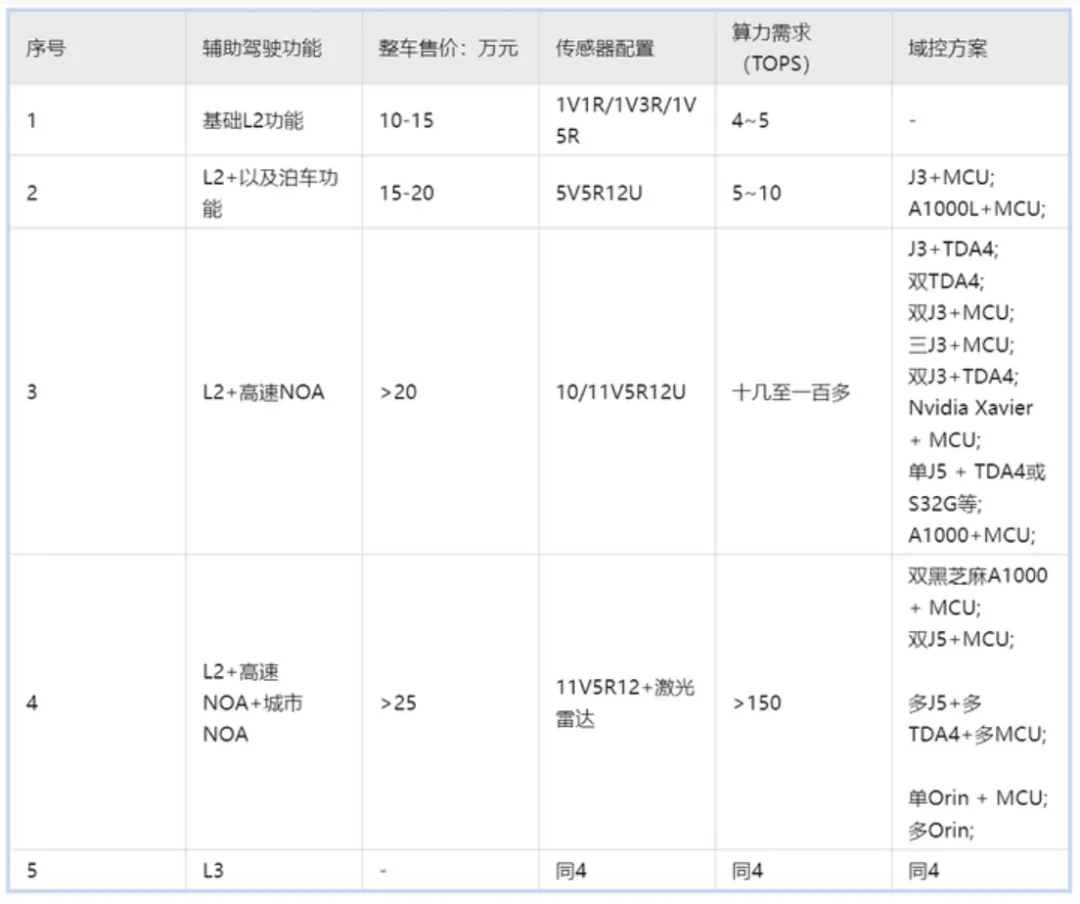
Automatic driving domain controller solution
Hardware Solutions
Two mainstream hardware solutions:
1) TC297+TDA2 platform based on the application of automatic parking
2) TC397+TDA4 platform provides higher computing power and richer memory resources and interfaces, based on the application of valet parking
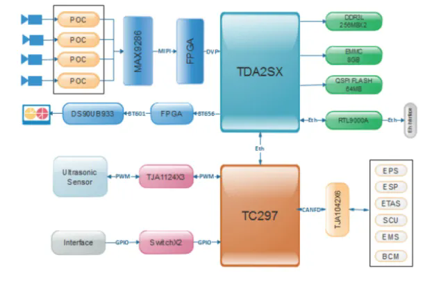
TC297+TDA2 scheme
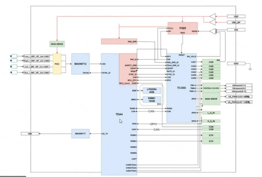
TC397+TDA4 scheme
The following figure is the solution of Yingchi Technology 3 J3+S32G. It can be seen that a J3 is responsible for 8M main camera processing, a J3 is responsible for peripheral and rearview processing, Lesson 3 J3 is responsible for circumnavigation processing, and finally M7 core in S32G is responsible for control (there are three pairs of M7 lock step nuclei in S32G)

Software solution
Support flexible software architecture solutions for MCU and SOC to meet the data analysis and transmission of multiple types of sensors, support customer development and functional safety requirements.
1) MCU end based on Classic Autosar standard architecture
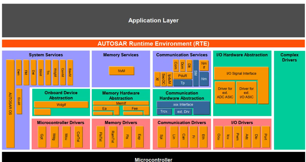
2) SOC supports Linux/QNX/VxWorks operating system and Adaptive Autosar architecture
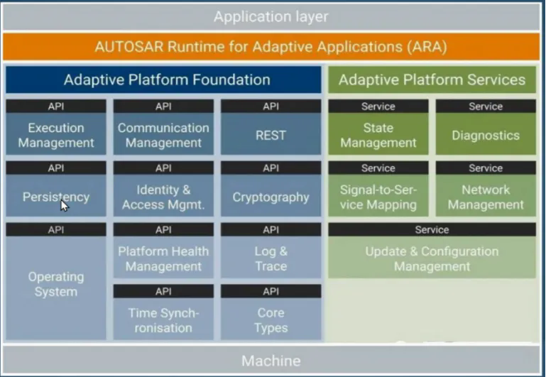
Inline chip solution
Low-end line mooring integrated chip: TDA4, J3
High-end line Mooring integrated chip: OrinX, Senteng 610
It can be seen that the previous parking system was composed of a separate controller and sensor, and now they are doing a parking and cabin parking integrated program, integrating the functions of a parking and driving into a controller to develop and realize, or integrating the parking software into the cockpit control. The above two methods not only reduce the system cost, but also improve the integration of the system. This trend is also developing and "convergent" for the upcoming cockpit integrated solution and even the vehicle central controller architecture.
2.3 Actuator
Theactuator is mainly composed of 4 parts (all essential) :
VCU(Vehicle controller) : In the automatic parking function, VCU has two main functions, responding to gear switching and responding to torque output to achieve vehicle movement;
ESP (Electronic stability program) : The main function is to receive deceleration information to achieve vehicle braking. Bosch currently offers ESP that supports two brake interfaces, CDDS and CDDAP. CDDAP is a special interface for parking, which can realize higher precision braking by sending information such as remaining braking distance and emergency braking, and its accuracy can generally be controlled within 10cm. CDDAP also provides interfaces such as two-stage pressure relief for starting on ramps.
EPB (electronic brake) : the main function is to park the vehicle after the end of parking, in addition, EPB can also be used as a brake redundancy backup, EPB generally supports a direct response below 3km/h, which can make the vehicle stop. For key parking and mobile parking, brake redundancy backup is necessary. For some vehicles, the EPB controller is integrated into the ESP due to cost considerations. In this case, the ESP is abnormal, and the EPB cannot play the role of brake backup.
EPS(electronic steering power) : The main role is to rotate the steering wheel to achieve lateral control of the vehicle. EPS interface has two, torque control and Angle control. Torque control is generally used in lane keeping systems. Parking mainly uses Angle control, which has higher control precision and better response consistency, and is convenient for the realization of trajectory tracking algorithm.
2.4 Other Associated Systems
IP(instrument) : The main function is to display parking information and prompt the parking process.
HUT(navigation host) : The main function is to display parking animation and provide parking buttons;
BCM(Body Controller) : Provides vehicle door status. When the door is opened, the parking system should be disabled. The opening of the door will affect the accuracy of the camera's parking spot recognition. In addition, when the door is opened, the vehicle boundary will change, and there is a certain risk of collision.
PEPS(Keyless entry system) : forward the key signal to achieve remote key parking.
BLE (Bluetooth module) : can be integrated in the large screen, but to meet a certain range of connection distance, mainly used for mobile phone control parking. To ensure system security and prevent Bluetooth channel hijacking by malicious attacks, you can use packet encryption and timestamp to ensure system security. Mobile parking does not use 4G or 5G networks as connection channels because network signals are susceptible to environmental interference and network delays. For example, some underground parking has no network signal, and parking will not be available. In addition, regarding the network delay, if there is an anomaly during the mobile phone parking process, it is necessary to ensure that the vehicle exits the parking immediately.

算法
Automatic parking is generally divided into: environment perception, parking space detection and recognition, parking path planning, parking path following control and analog display five links, so the automatic parking algorithm module can be refined into: sensor fusion, trajectory planning, vehicle control, obstacle avoidance module, state management module, positioning module. Algorithm block diagram is as follows:
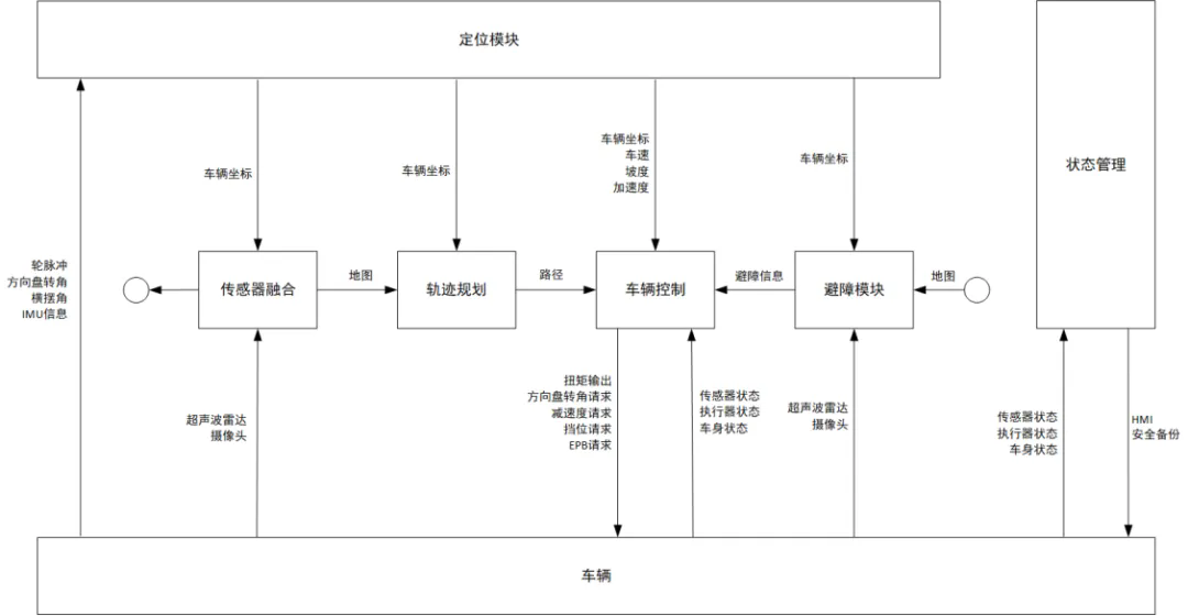
Automatic parking algorithm block diagram
3.1 Orientation
The key technologies of mapping and positioning module mainly include vehicle positioning and parking map scanning. This module needs to complete the perception and modeling of the information around the vehicle, the positioning and tracking feedback of the vehicle itself, and the map and positioning information established are the fundamental basis of the automatic parking path planning and control decision-making module, and are also the direct factors determining the quality of the automatic parking of the vehicle. According to the different vehicle configuration, the common positioning technology of automatic parking is summarized as follows.
3.1.1 Dead reckoning Positioning technology
The positioning based on dead reckoning mainly uses inertial navigation system and odometer.
The inertial navigation system is based on the principle of inertia, and the vehicle IMU outputs six degrees of freedom information, including x, y, z, roll, pitch and yaw, all day long. The basic principle is to first calculate the attitude by integrating the measured angular velocity, project the measured acceleration into the navigation coordinate system according to the attitude information, and then integrate the projected acceleration to calculate the position after removing gravity [4]. Therefore, systematic errors will accumulate over time and become the biggest problem in inertial navigation.
odometer positioning is based on the application of vehicle wheel speed sensor, through the calibration method to obtain the distance of the unit pulse, and then calculate the distance of the wheel by counting the pulse, and then obtain the vehicle's heading Angle and current pose. Taking the vehicle equipped with sensors as shown in Figure 2, the odometer location algorithm based on wheel pulse is introduced as follows.
(1) Pulse coefficient calibration
The wheel pulse sensor is used as the main sensor of the positioning module, and the distance traveled by the unit pulse of the vehicle can be obtained through calibration, that is, the pulse coefficient. The pulse coefficients of the left and right sides of the driving wheel of the vehicle are respectively calibrated, and the driving distance of the vehicle can be obtained through pulse counting, as shown in formula (1) (2) :
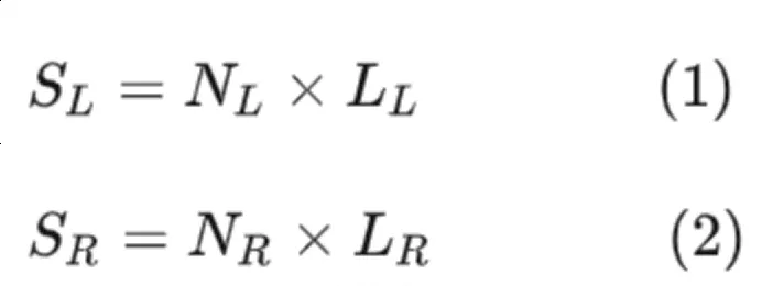 In the
 formula, SL and SR respectively represent the distance of the left driving wheel and the right driving wheel; NL and NR represent the pulse coefficients of the left and right driving wheels respectively. LL and LR represent left and right drive wheel pulse counts respectively.
(2) Vehicle EPS Angle calibration
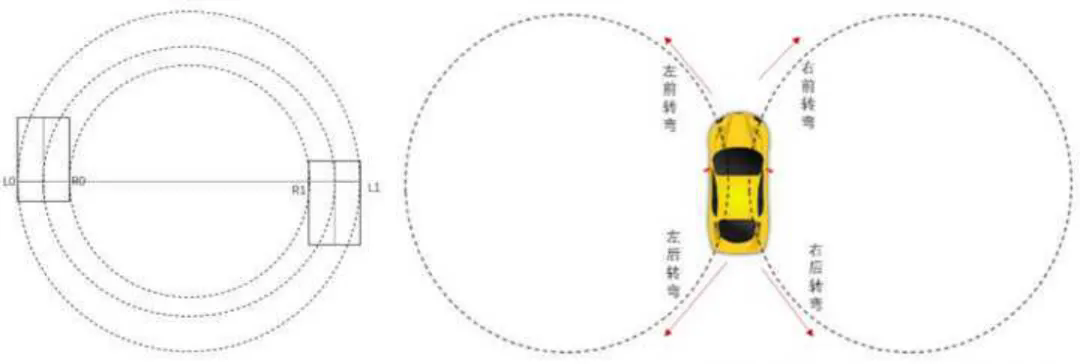
The semicircle calibration method was used to calibrate EPS Angle and turning radius, and the principle was shown in Figure 4. First, the vehicle to be calibrated is parked at the test site marked with a straight line, the center of the rear axle of the vehicle is coincident with the straight line, the EPS Angle is controlled as the value to be calibrated, and the location of the outer alignment of the two rear wheels is marked as L0L_0 and R0R_0. Then, keep the EPS Angle unchanged, the vehicle drives steadily at a lower speed and turns 180°. Mark the locations outside the two rear wheels as L1L_1 and R1R_1, and measure the distances between (L0L_0, L1L_1) and (R0R_0, R1R_1) as DLD_L and DRD_R, respectively. Calculate the turning radius of the vehicle as R=DL+DR2R=\frac{D_L+D_R}{2}. EPS Angle and turning radius were recorded in the table shown in Figure 5 for positioning table lookup calculation.

(3) Positioning tracking calculation
Rear-wheel drive, front-wheel steering vehicles as an example, the vehicle positioning calculation model as shown in Figure 6 was established.
 <
<
The driving distance of the left and right wheels can be obtained by calibrating the pulse coefficients of the left and right wheels, as shown in formula (1) (2), the driving distance of the rear axle center of the vehicle can be obtained as follows: S=SL+SR2 (3)S=\frac{S_L+S_R}{2}
The turning radius R under the current EPS Angle is obtained by using the table lookup method (FIG. 5). As shown in FIG. 6:
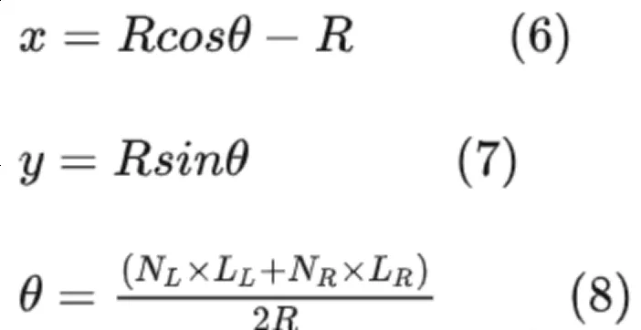
Therefore, the positioning module outputs vehicle attitude information as follows:
3.1.2 IMU+ Wheel Speed Fusion Positioning
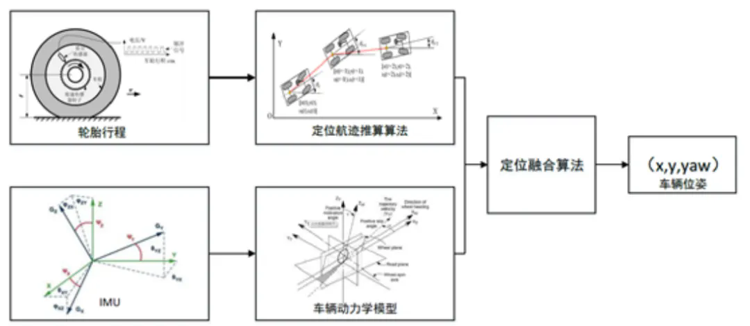
Thedead reckoning algorithm is suitable for the position and pose positioning of short travel vehicles, but there are some errors in this method. Therefore, it is necessary to combine other methods to locate. In this scheme, a combination of IMU and vehicle dynamics model is adopted to calculate high-precision pose changes in a short time by position estimation algorithm, and the final vehicle pose is calculated by positioning fusion algorithm. The method flow is shown as follows:
Dead reckoning process
3.1.3 Environment feature matching positioning technology
The most typical application of location technology based on environmental feature matching is Lidar technology. Lidar uses laser as carrier to form data in the form of point cloud, and carries out range measurement and identification by transmitting signal and reflecting signal. Lidar is mainly composed of a laser transmitter, a laser receiver and an optical scanning mirror. The basic working process is that the laser transmitting system converts electrical pulses into light pulses. The laser pulses are diffused on the surface of obstacles, and some of the reflected beams return in the same direction as the incident beams. When the speed of light is known, the distance is calculated by measuring the time difference between the transmitted pulse and the received pulse.
Dead reckoning positioning is not easy to be interfered by the external environment (illumination, environmental complexity, etc.), the sensor is mature, the cost is low, the calculation is small, and the real-time performance is high. Although it is a relative positioning method, it will be affected by cumulative errors, but considering that for the parking system, the vehicle driving distance is short, Therefore, the accumulated error will not cause too much impact on the operation of the system. Therefore, in engineering practice, relative positioning method is the most used positioning method for low-level driving assistance systems at present.
3.2 Perception
The perception algorithm of automatic parking system mainly includes two parts: parking space recognition and obstacle recognition. The obstacle recognition is similar to the driving scene design, so the detection algorithm of parking space is mainly analyzed.
3.2.1 Free Space Based approach
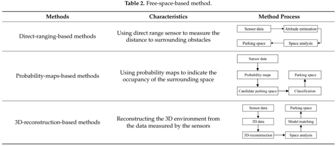
The free space based method is to detect the available parking space by identifying the surrounding environment of adjacent vehicles and analyzing the spatial structure around the vehicles. Commonly used sensors are ultrasonic sensors, laser sensors, stereo cameras, depth cameras and other cameras. These sensors can sense the environment around the vehicle and provide reliable reference data for parking spot detection. According to the different methods of parking space recognition, the methods based on free space can be further divided into the methods based on direct ranging, probability graph and three-dimensional reconstruction. The characteristics of these three methods are analyzed and described below, as shown in Table 2
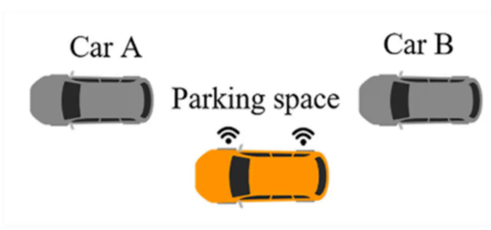
Parking space detection method based on direct distance measurement
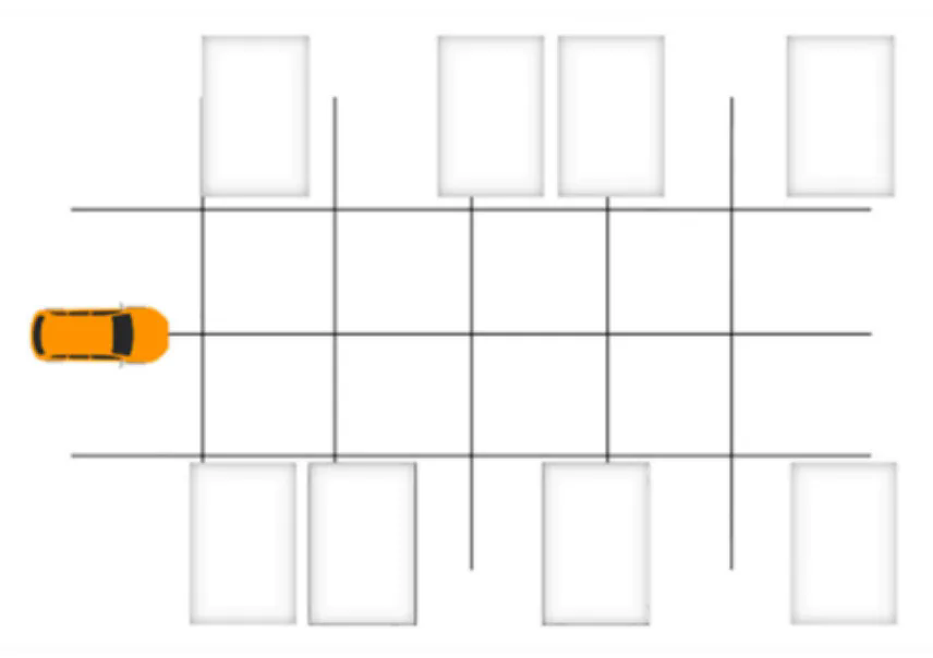
Method based on direct distance measurement
Parking space Detection Method based on probability graph
At present, there are many problems in parking space detection methods based on direct ranging. So the researchers used a cartographic representation method and mathematical statistics to divide the environment into a series of small grids, each with a possible value representing the probability that the grid would be occupied. Parking Spaces around vehicles are estimated by grid occupancy. This method is called probability graph-based parking space detection method.
Occupied raster map
Parking space Detection Method based on 3D reconstruction
The parking space detection method based on 3D reconstruction realizes the detection of parking space by rebuilding the three-dimensional space model around the vehicle. In the traditional 3D reconstruction process, there are a large number of pseudo-3D points, and the density of 3D points has a linear relationship with the number of detected features, which cannot be controlled. By improving the tracking efficiency and density of 3D points and rebuilding the obstacle model, the detection accuracy of parking Spaces can be improved.
Summary
At present, the method of detecting parking Spaces based on free space has become the mainstream method, which only needs to install cheap ranging sensors on the vehicle, at the same time, this method also has certain disadvantages. The detection performance of this method depends entirely on the vehicles parked adjacent to the parking space, and this method will fail when there are no parked vehicles around.
3.2.2 Method based on Parking space marking
Free space based parking space detection method is the most widely used method, but its performance depends on the attitude of adjacent vehicles and the measurement accuracy of the sensors used. Therefore, if there is no adjacent vehicle, the parking space detection method based on free space cannot work properly and cannot meet the driver's demand for parking space detection. Therefore, the researchers proposed a parking space detection method based on parking space markers, which uses computer vision technology to determine the location of parking Spaces by recognizing parking space markers from images. According to the different detection techniques, it can be divided into three categories: the method based on linear detection, the method based on corner detection and the method based on learning. This section analyzes and describes these three detection methods, as shown in Table 3.
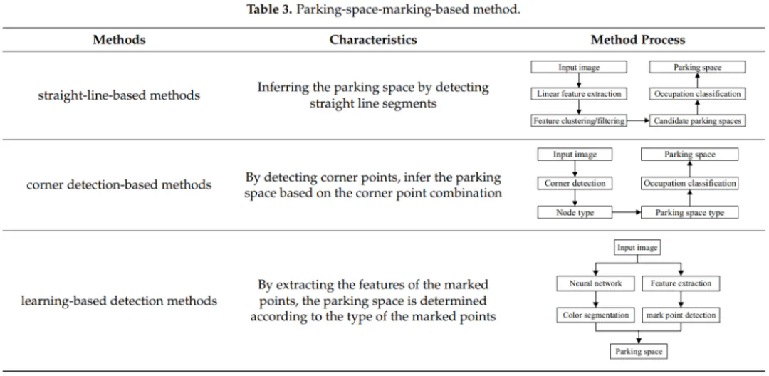
Parking space Detection Method based on line
Parking space marker refers to a parking space in a particular parking lot consisting of guidelines and dividers attached to the ground. There are many types, such as rectangular parking Spaces, parallelogram parking Spaces and diamond parking Spaces. Since parking markings are made up of straight segments, detecting a straight line is crucial to finding a parking space.
Parking space Detection Method based on corner points
The method based on the traditional linear detection of parking Spaces can only detect one or two types of parking Spaces, but there are many types of parking Spaces, such as diamond or parallelogram. The parking space detection method based on corner features can detect various parking space types and realize various parking operations.
Learning based approach
Almost all existing state-of-the-art methods in the field are based on low-level visual features, such as line segments and corner points, and detect some low-level visual algorithms. Due to noise, clutter, or lighting changes caused by non-repeatable environmental changes, these features cannot be clearly distinguished, and worse, they are unstable. Therefore, how to use visual methods to efficiently and accurately detect parking Spaces in complex and changeable environments is still a difficult problem. To solve this problem, the researchers used deep learning techniques to build a neural network model through a learning-based approach, train the model from a large number of positive and negative samples, and implement the detection of parking Spaces.Summary: The parking marker based approach identifies parking Spaces by analyzing markings on the road, in contrast to the free-space based approach, whose performance does not depend on the presence and location of adjacent parked vehicles. However, these methods can only work properly in parking lots with parking space markers, and are not suitable for situations where parking space markers are obscured or blurred.
3.3 Planning
Focus to the millimeter-level trajectory planning According to the input behavior decision information, combined with real-time vehicle pose information, local environment information, global path reference information, etc., under the guidance of the spirit of "safety, comfort and efficiency", plan and generate a smooth trajectory trajectory (including driving trajectory, speed, direction, etc.) that meets specific constraints, and input it to the control executive layer.
3.3.1 Hybrid A*
Hybrid A* is A heuristic search under continuous coordinate system. Based on grid map, Hybrid A* selects a point satisfying the 3d continuous state of the vehicle and assigns the loss value to the point. In other words, the search space of Hybrid A* not only considers the expansion of x and y directions, but also considers the exploration of heading Angle direction to ensure that the generated trajectory meets the constraints of vehicle dynamics.

The trajectory planned by
The trajectory planned by Hybrid A* consists of two parts. One part is the path connected by the exploration nodes considering vehicle dynamics; Part of it is the path connecting the intermediate point pose with the target pose using the ReedSheeps curve. ReedSheeps curve is used to connect the current node and the target node, and collision detection is performed on the trajectory. If there is no collision, the search is terminated, and the planned trajectory is path1 from the current path to the target node + path2 from the current node to the start node. If there is a collision, the curve is abandoned and the node is found again from OpenList and the search continues.
3.3.2 Arc Linear geometry
Given a starting point (x,y,theta) and an ending point (x,y,theta), there can only be three unknowns by connecting them with arc-lines. Taking a line + an arc as an example, our three unknowns can be set as line length l, arc length s and arc radius r, and these three unknowns can be obtained by combining the starting point and ending point equations.
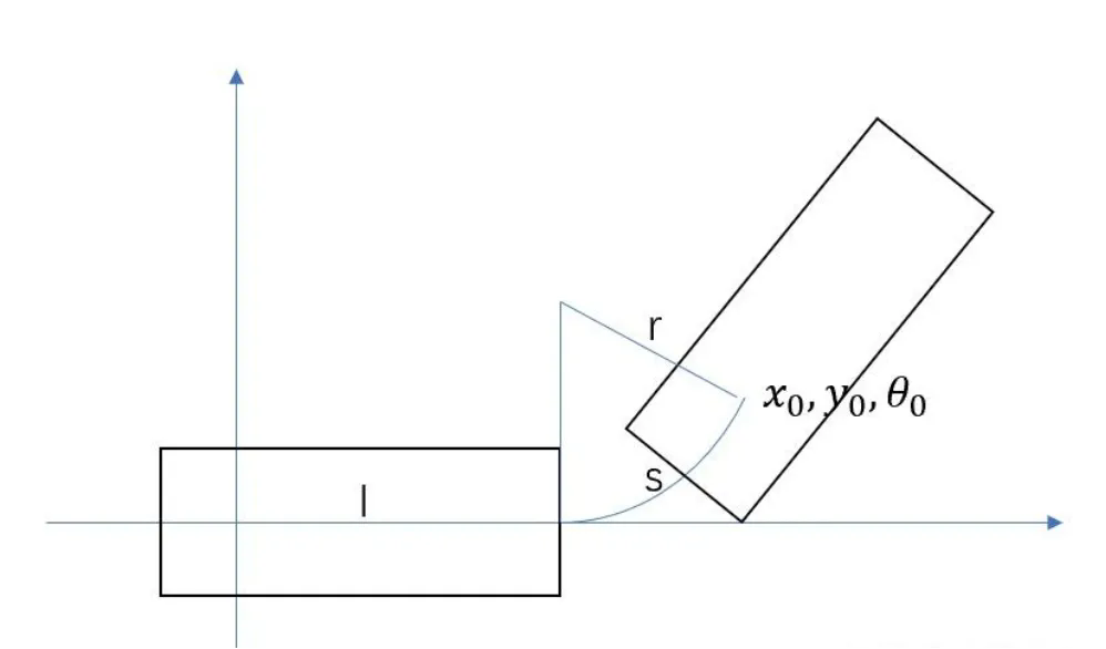
To facilitate the solution, we normalize the starting point so that we can list three sets of equations.
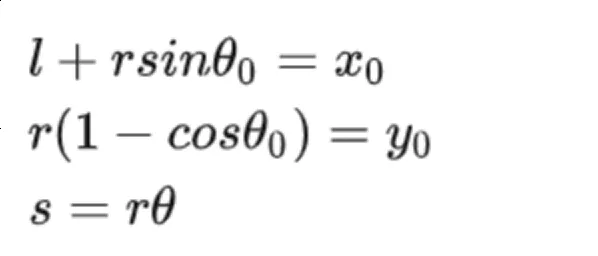
The planning method based on arc line is strongly dependent on human prior knowledge, taking reversing into the warehouse as an example, generally speaking, we will first try a mooring. If you can't park in one go, you will drive near the parking space and try to straighten the car, then drive forward and try to park backwards. For the scene of one parking, we directly use the straight-arc or arc-straight or straight-arc - straight line connection, if the connection is successful and there is no collision, it means that this parking space can be parked in one. If you can't park in one, you can first try to drive the car near the parking space, and then try to park in. We sample the position and Angle near the parking space, let the car drive to the sampling point, and then turn the steering wheel left forward for a distance, and then reverse into the park.

In the same way, we can go forward and back several times and park in the parking space.
3.4 Control
3.4.1 Vehicle Kinematics model
The control method based on vehicle kinematics model mainly considers the influence of vehicle kinematics constraints on vehicle control. First, look at common vehicle kinematics models:
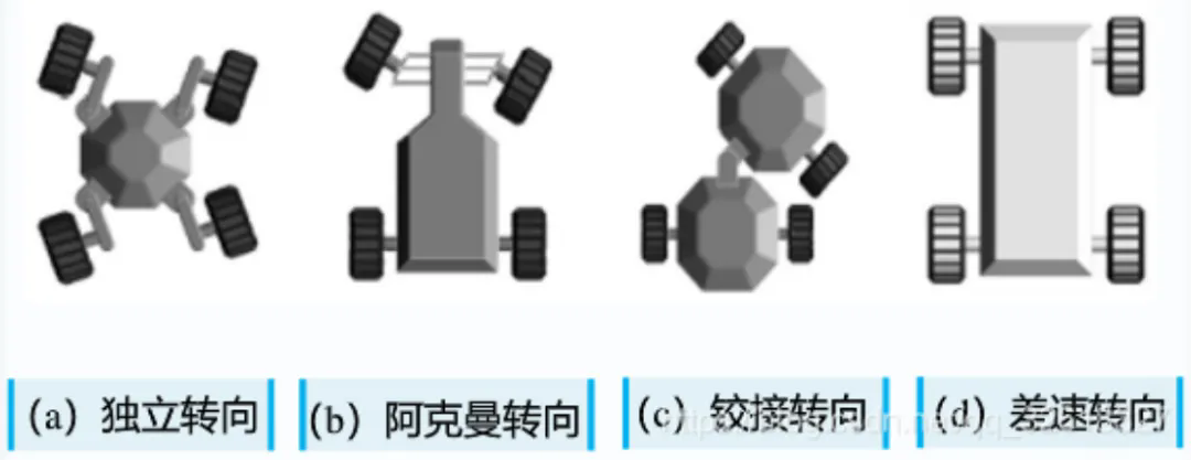
The usual car is an Ackerman steering, which can often be simplified into a two-wheeled bicycle model
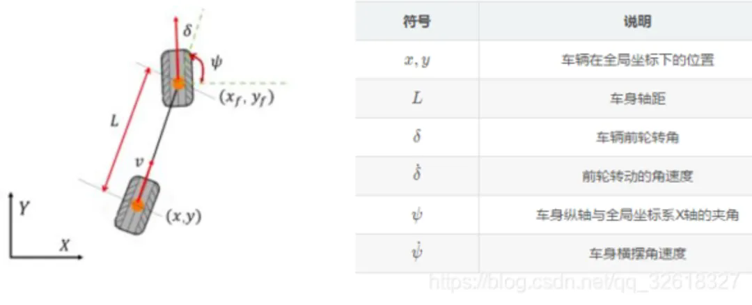
It assumes that the front and rear wheels of the vehicle are rigid bodies and can only move forward in the direction of wheel rolling without lateral sliding. The motion differential equation of the bicycle model can be obtained from the above assumptions as follows:

Relation between angular velocity and angular velocity: v=ωr, that is, ω=v/r, so here
Others are simpler and will not be explained.
3.4.2 Horizontal control
Rear wheel feedback is a method that uses the path tracking deviation of the rear wheel center to calculate the steering control quantity

According to the kinematic equation (2-1) and the geometric relationship between the rear wheels of the vehicle and the reference path
The reference path coordinate system can be derived (�, �)
The rate of change of (�, �, ψ�) in the Ferent coordinate system is: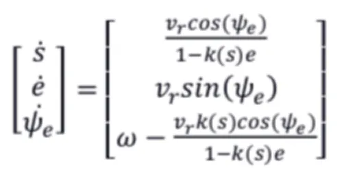
Frenet coordinate system uses the center line of the road as a reference line, using the tangent vector and normal vector of the reference line to establish a coordinate system, then based on the position of the reference line, you can use the longitudinal distance and horizontal distance to describe any position, while the longitudinal and horizontal speed, acceleration, acceleration and other information is more convenient to calculate.
For a secondary continuously derivable reference line, it is necessary to design the body yaw speed to ensure local asymptotic convergence under the Lyaplov equation:
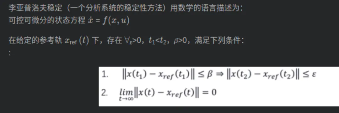
For Lyaplov stability is also divided into asymptotic stability and exponential stability. Lyaplov's stability theory starts from the point of view of energy. The energy of the system is constantly changing (increasing or decreasing) over time, and in a finite time, the system tends to be stable and the energy no longer changes. In this case, the energy of the system at time k+1 minus the energy at time k is < 0, which is V(k+1)-V(k)< 0, V represents the energy function. Asymptotic stability means that for a time-varying system, independent of time t1 under condition (1), exponential stability means that the convergence rate decreases exponentially. For the rear wheel feedback algorithm, in order to ensure the Lyaplov stability of the vehicle, the body yaw speed can be expressed as the following formula:
Where, �ψ is the yaw Angle deviation feedback control gain, �e is the lateral position deviation feedback control gain
Therefore, according to the kinematics equation, it can be obtained that the front wheel Angle is:
3.4.3 Vertical Control
Longitudinal control is mainly speed control, through the control of the brake, throttle, gear, etc., to achieve the control of the speed, for the automatic vehicle, the control object is actually the brake and throttle.

Principle of vertical control
The working principle of longitudinal control is shown in the figure. It is mainly composed of "displacement-velocity closed-loop PID controller", "speed-acceleration closed-loop PID controller" and "speed-acceleration-brake/throttle" open-loop controller.

Industry status
In recent years, major Oems have increased their investment in automatic parking systems and launched models equipped with automatic parking systems, and the penetration rate of automatic parking in front of new cars in China has continued to rise. Data show that from January to May 2022, the APA carrying capacity of new cars in China reached 957,000, and the APA penetration rate reached 13.6%. In 2021, the APA carrying capacity of new cars in China reached 2.437 million, and the APA penetration rate reached 11.9%, an increase of 17.8%. The following compares the automatic parking and loading information of several mainstream Oems:

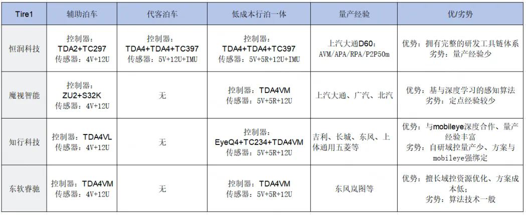
Mainstream supplier solutions, including Heng Technology, Magic vision Intelligence, Zhixing Technology, Neusoft Smart.

Look to the future
From APA to AVP, automatic parking technology is constantly improving, and the automatic driving industry is also constantly developing. For automatic parking, or for any product, innovation is always the inexhaustible vitality of this product. Back to our theme, for automatic parking let's imagine a story: one day a novice driver driving to work, to the parking lot after many attempts can not park the car into a small (may not be so small) parking space, then he (she) has been late, the car suddenly came a voice: you go to work first, I will help you park! He (she) burst into tears and said: Thank you! Then immediately get off and run to the elevator, while the car slowly parked itself into the parking space.
Although the above story is made up by ourselves, this may be the original intention of the birth of automatic parking. The beginning of the article mentioned the evolution of automatic parking technology, in fact, a closer look is the continuous innovation and iteration of this technology application scenario. From the very beginning, just parking the car into the parking space, to the rear remote control parking, and then to valet parking, are constantly innovating and expanding the scene to solve the needs of users: I can not park my car into the parking space by myself. I pulled into the parking space but it was too narrow for me to get out. I didn't have time to park... In the face of such a demand, the application scenarios of automatic parking continue to innovate and increase, the user's pain points are solved, and the experience continues to improve. We have reason to believe that in the near future, the fully autonomous driving system will be landed on a scale, which will be another scene!Disclaimer:
All the works marked "source: XXX (non-intelligent car technology)" in this public number are reproduced from other media, reproduced for the purpose of transmitting and sharing more information, does not mean that the platform agrees with its views and is responsible for its authenticity, copyright belongs to the original author, if there is infringement, please contact us to delete.